2024 – 2025
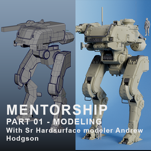
I’ve started a 3D modeling mentorship with Senior Hardsurface modeler Andrew Hodgson
The purpose of this project is to push the model as far as possible, following industry methods and pipeline. That is the goal.
I’ve been following and viewing Andrew’s streams and videos since 2019, learning a lot from them, and I’ve always wanted to work with him. That mentorship is a way to learn the industry ways in-depth, and create a solid portfolio piece.
I will document the process and sharing screenshots of my work here, for anyone that might find it useful
Before starting, here’s Andrew website, be sure to check out his work : https://andrew-hodgson.com/
Concept choice
After my portfolio review by Andrew, we talked about what could be the best to work on for me. We agreed that I had a lot of vehicles, and that a robot or a mecha would be a great addition to my portfolio.
After some scouting, we agreed on a concept by Brian Sum.
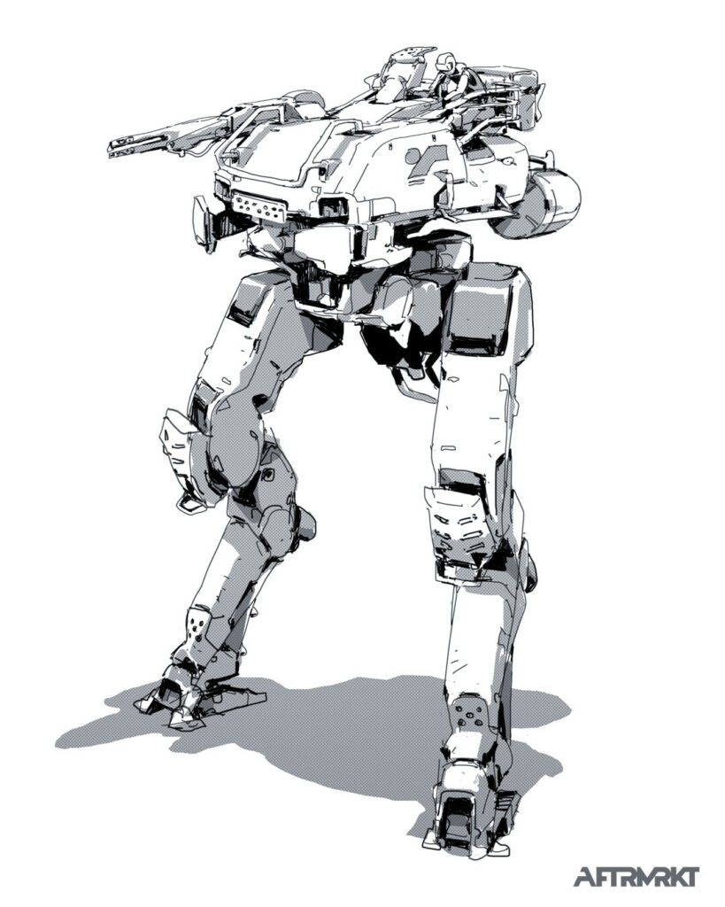
As the point was to complete my skills set, this concept involve a lot of creative problem solving.
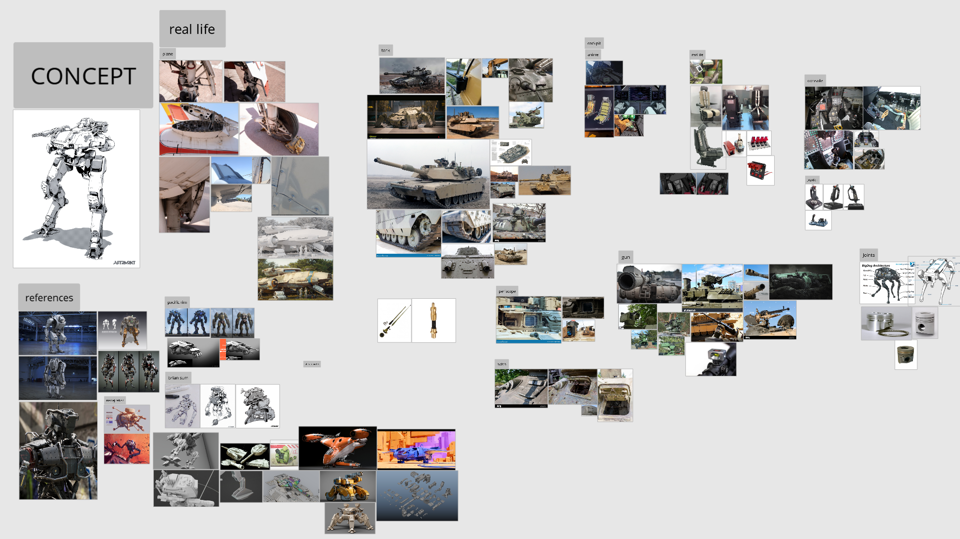
Gathering reference
For the sake of the project’s documentation, I’ll share my PureRef here. Gathering reference throughout the project is really important. For instance, the real tank photos and documentation came later, and helped me refine the robot and make it realistic (for the big body parts, panels, or little details to add on the surface).
Part 01 – Blocking
First step, the blocking. According to my habit, I started with shaping my forms with planes.
After our first session, Andrew showed me a new method (at least to me) which consist of blocking with closed shapes, super loose and basic geometry.
That method is helpful to have a quick idea of proportions, and helps the transitions between production teams (Rigging, Animation…), especially with mechanism, as I’ll talk about later.

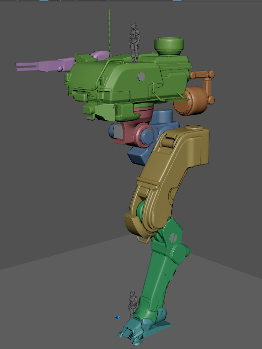
Thinking the mechanism ahead
As you can see in the previous screenshot, we planned the joints rotation while blocking. The big parts of the robot were created according to expected joint rotation, so that there is no intersection and mesh colliding while moving the leg for instance.
Blocking the different articulations and the things that rotates with them with color was a cool trick from Andrew, that I’ve never thought to do. As the concept is loose, this helped defining the big shapes better, and have them working with the rotations.
That is how the red body part was define, with Andrew’s advices on keeping the model coherent (the circular transition from red to green on the screenshot, square to circular).
Material planning and blocking refining
Once we got (roughly) the robot’s articulations planned, we started to think about materials. That’s where the real life tanks documentation came in handy.
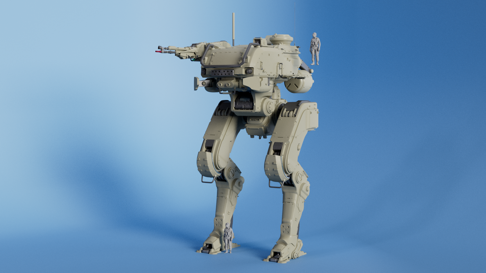
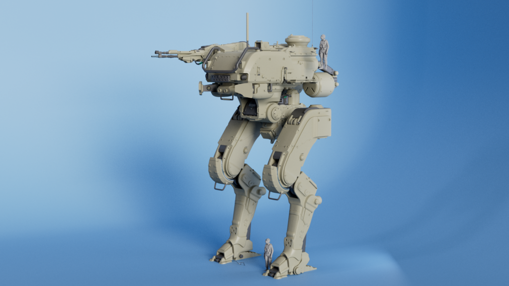
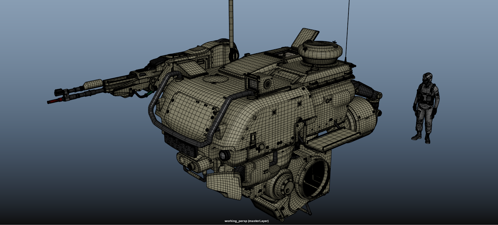
On the modeling side, we settled for good the proportions, and I started refining and doing some panels.
A man was also added, to understand better the scale of the robot (and with that, the scale of the details on it).


Part 02 – Approval of the blocking, start of detailing
Head and gun
The blocking of the head, gun, and legs now approved by Andrew, it was time for me to start looking up little details on the concept, and how it could translate to 3D, with the help of photos of real tanks.
First, my focus was set on the head, and the gun.
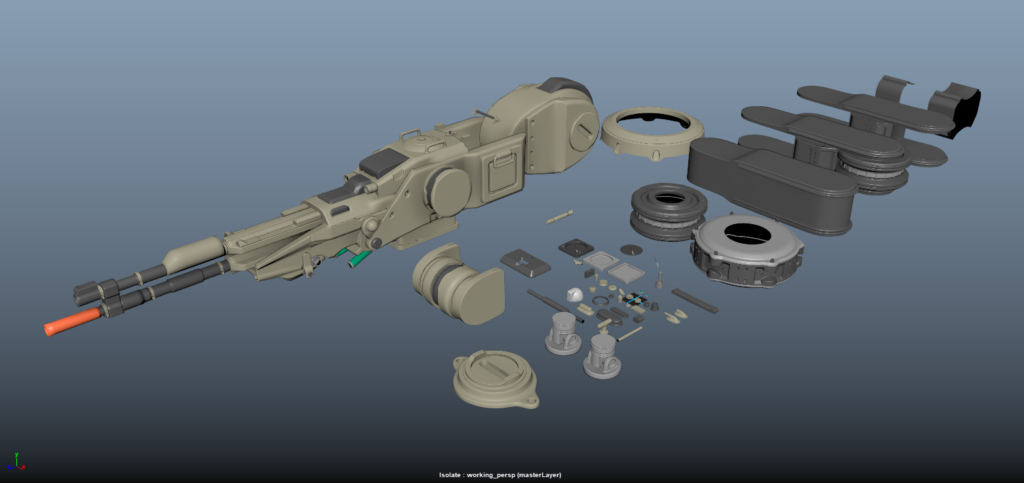
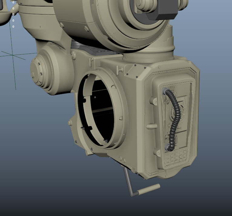
During my project, I built a small kitbash kit, screws, mechanical elements of all sorts, details, handles, some of it were created directly on the robot and duplicated. Before duplicating those small details, I made sure the UV’s for each one were unwrapped and correctly lined up.


Body and leg
After I wrapped up the head and the body, it was time to do the leg (without including the body/leg rotation and foot). At this stage the whole head and body was finished, tripled edge. I didn’t like much the design I made of the body, so I started over that part. It’s important to keep the creasing and the low resolution until the final approval.
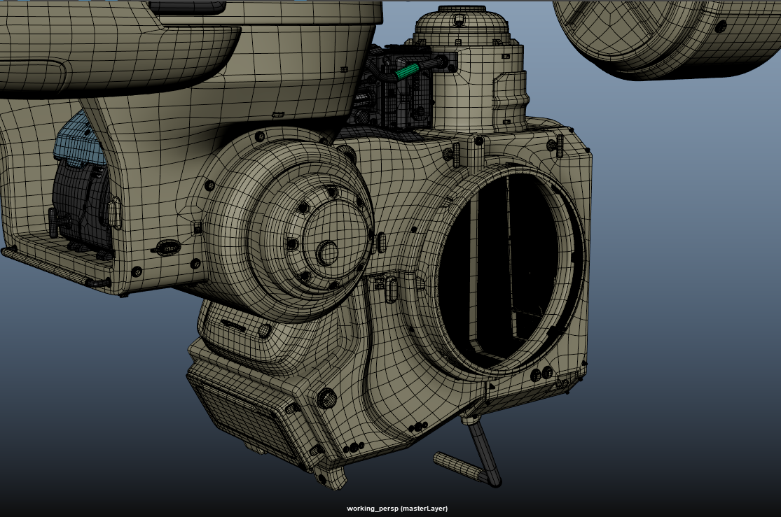
For this documentation, you’ll notice the robot is pretty onesided, that’s because I’m making sure the left side is well rounded, approved and UVed, before mirroring it to the right side. This will come at the end, when I’ll do UV layout.
Part 03 – Mechanics and rotations
Leg, Body, Foot
It’s important to notice that at this stage, the whole robot, except these mechanical elements and rotations, is pretty finished. We can sum up by saying the beige things are done. We tried it with our blocked rotations, nothing collides, everything works. Now it was time to detail it.
As always with new methods in this project, Andrew showed me the good direction and I built from there.
Foot
The foot was already quite advanced, but we had to make sure the rotations made sense and was realistically working. That is where keyframes is used, to simulate the maximum and minimum amplitude of the foot, and built the mesh accordingly.
Then, it was mostly kitbashing, matching other mechanical elements aesthetic, and building around that idea.
We used a basic ball joint to trick the complexity of a foot articulation. As it is a robot, it is now fairly simple.
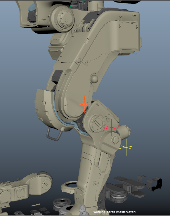
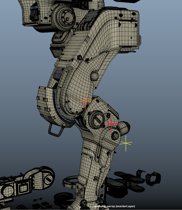
Knee, Shin
For the knee, as it was more cylindrical joint, locators were added at each pivot point, to duplicate the details around the circle easier.
You can see them here.
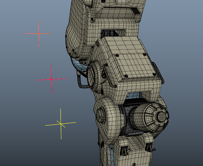
The knee rotations came in two main part, and one small one, the smaller being the knee, and the mains being the shin. The same workflow as the foot was used. Thanks to that workflow, I made insets here and there to make room for the piece to move, make more space for the articulation.
Body
This section will be quite small, as there’s no mechanical elements per say. I made it look like mechanical, but it is not actually articulating in any way.
Kitbash was the way, as often, but we have to be careful and keep it logical, and coherent.

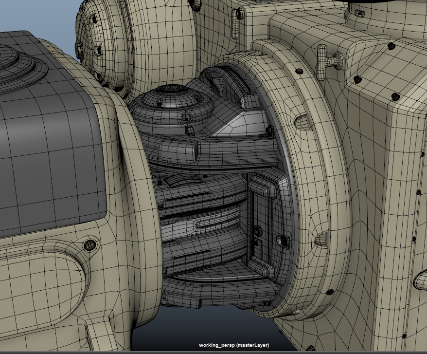
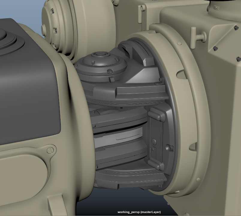
Leg joint
It was by far the hardest joint, at least to me. I’ve had a difficult time figuring it out, happily we sorted it out with Andrew, and now it’s way easier for me to make.
The leg has two rotation, one in the Y axis, and another one in the X axis. So it is made of two rotating elements, one for each.
The cool thing was that I already did the leg joint, and the foot joint, so now I had all those cool rotating elements in my kitbash kit. I built it from here.
I’ll first show how it works, then how it looks.
Conclusion
temporary
The modeling in Maya is now over as I’m writing this (6th March 2025). Now we’re heading towards Zbrush and displacement maps, and the UVs, most of it is already unwrapped but I’ve got the whole layout to do.
Let’s not forget about texturing, which I’ll do outside this mentorship, on my own.
Let’s not get to the thanks right now, it’s not over yet. I’ve already learned a lot, it’s not just about modeling, it’s about getting to know how to work in an industry pipeline. Knowing how departments work together, how to make my life as a modeler easier, and work smarter.
I’ve also learned how to make proper joints, which is a lot. On my older project I’ve always did it by eye. Now it is logical, coherent, and works in a realistic context.